OVERVIEW:
In the past when people had not yet invented the television, movie theaters used a very long ribbon of static images and rolled it very fast to create an illusion of a video clip. The device that helped them make movies using that method is called Zoetrope. Today, I’m gonna use the Arduino and a DC motor to simulate how Zoetrope works.
L293D H-BRIDGED INTEGRATED CIRCUIT:
The key to controlling the DC motor in this project is the H-bridge IC. It’s called integrated circuit because there are many tiny circuits inside it, sometimes identical ones. IC makes the circuit tidier and helps the wiring much easier. For instance, in this project, we can have the full control of the DC motor using this IC alone, whereas we had to use a MOSFET and a diode to operate the motor in the previous project.
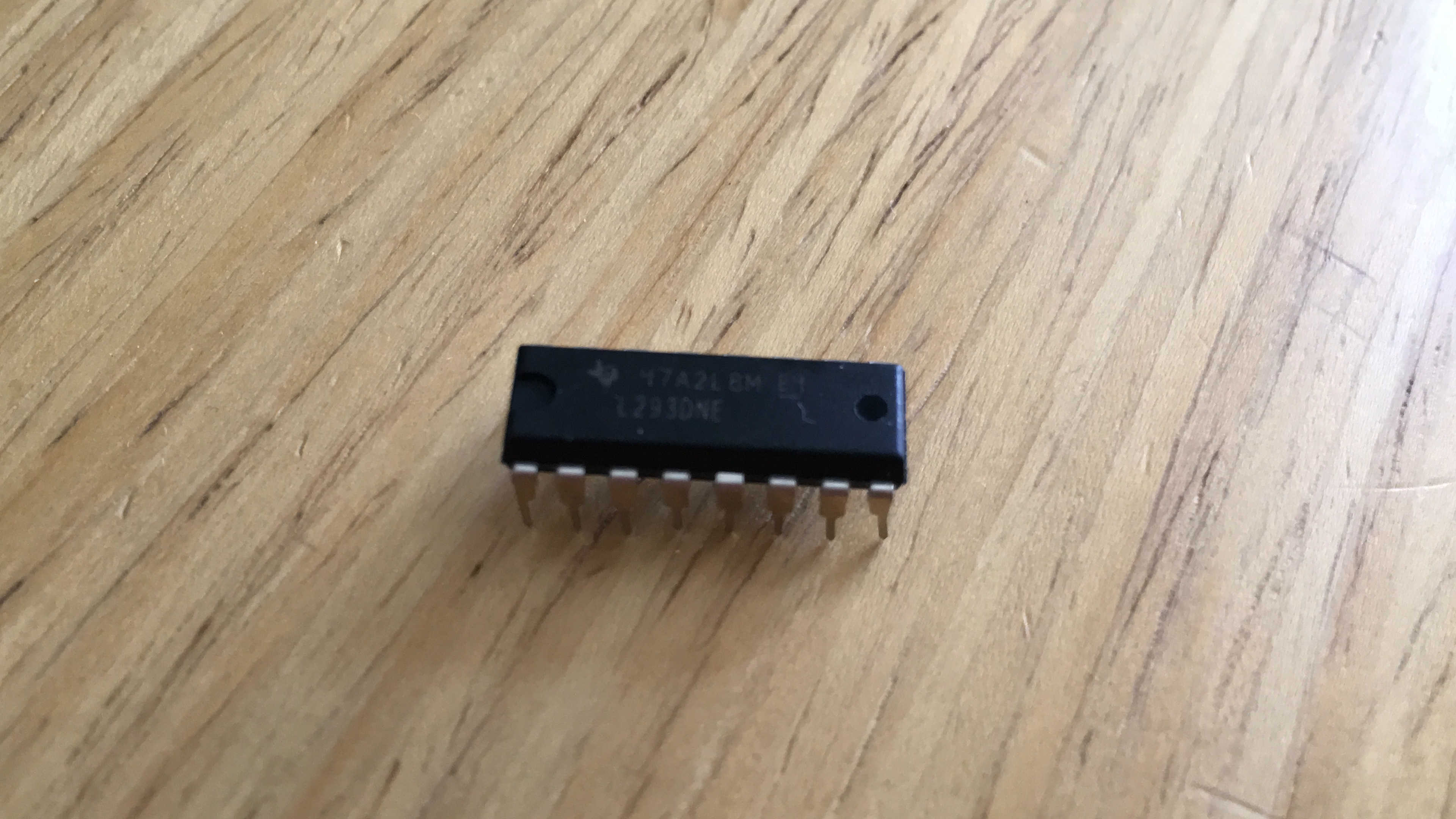
There is a variety of ICs, so understanding the structure of the one we want to use is crucial. In fact, we must look at the datasheet of an IC to know what exactly it does. Here is important information I snipped from the sheet
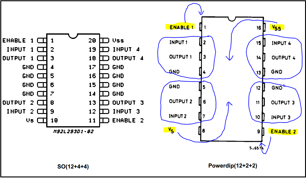
The figure on the left shows the pin structure of the 20-pin IC; I don’t use it, so I just ignore it. I’m using the 16-pin IC with 8 pins on each side. This structure can be divided into 4 identical parts. They are identical and have the same functions: input, output, and ground.
ENABLE 1is responsible for powering up the left bus which contains Circuit 1 and Circuit 2;ENABLE 2powers the right bus which contains circuit 3 and circuit 4. This time we connect~9toENABLE 1and leave theENABLE 2alone because we only use the left bus.- Since we plan to control the direction of the DC motor, we can hook one lead of the motor to
OUTPUT 1and the other lead toOUTPUT 2. Circuit 1 and Circuit 2 act like a polarity-controlled diode, which means they can change the one-way direction of the current according toINPUT 1andINPUT 2. IfINPUT 1 = HIGHandINPUT 2 = LOW, the current will flow fromOUTPUT 1toOUTPUT 2, resulting in the motor spinning in one direction; the vice versa is also true, resulting in the motor spinning in another direction. - Vs should be connected to
+9Vbecause the motor draws a lot of energy, whereas the Vss should be connected to+5Vof the Arduino.
PULSE-WIDTH MODULATION (PWM):
Pulse-width modulation is to modulate the width of the pulse. We can lengthen or shorten the HIGH duration of a signal without changing its frequency. For full information about PWM and analogWrite, please visit Arduino’s official tutorial.
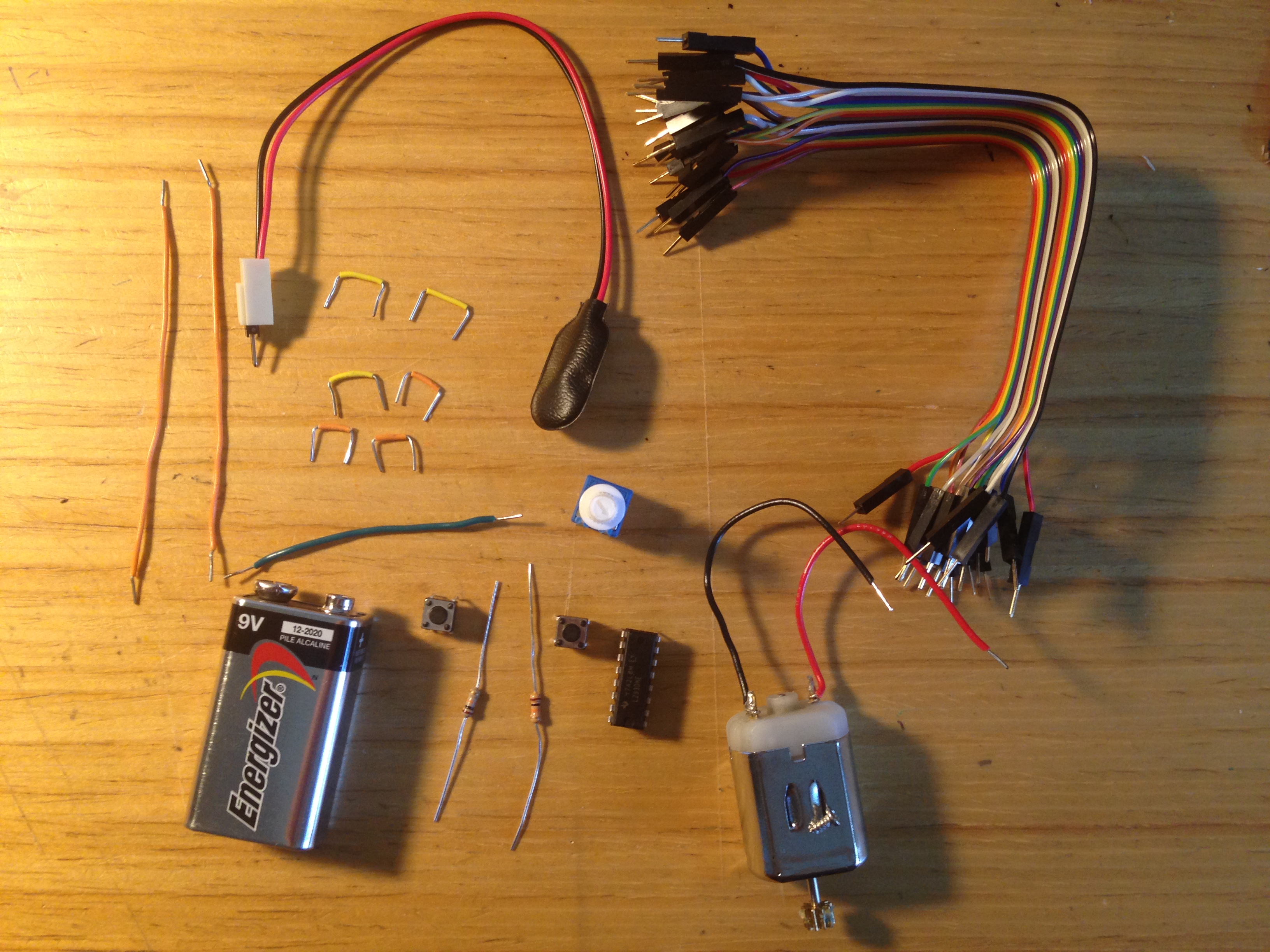
PARTS:
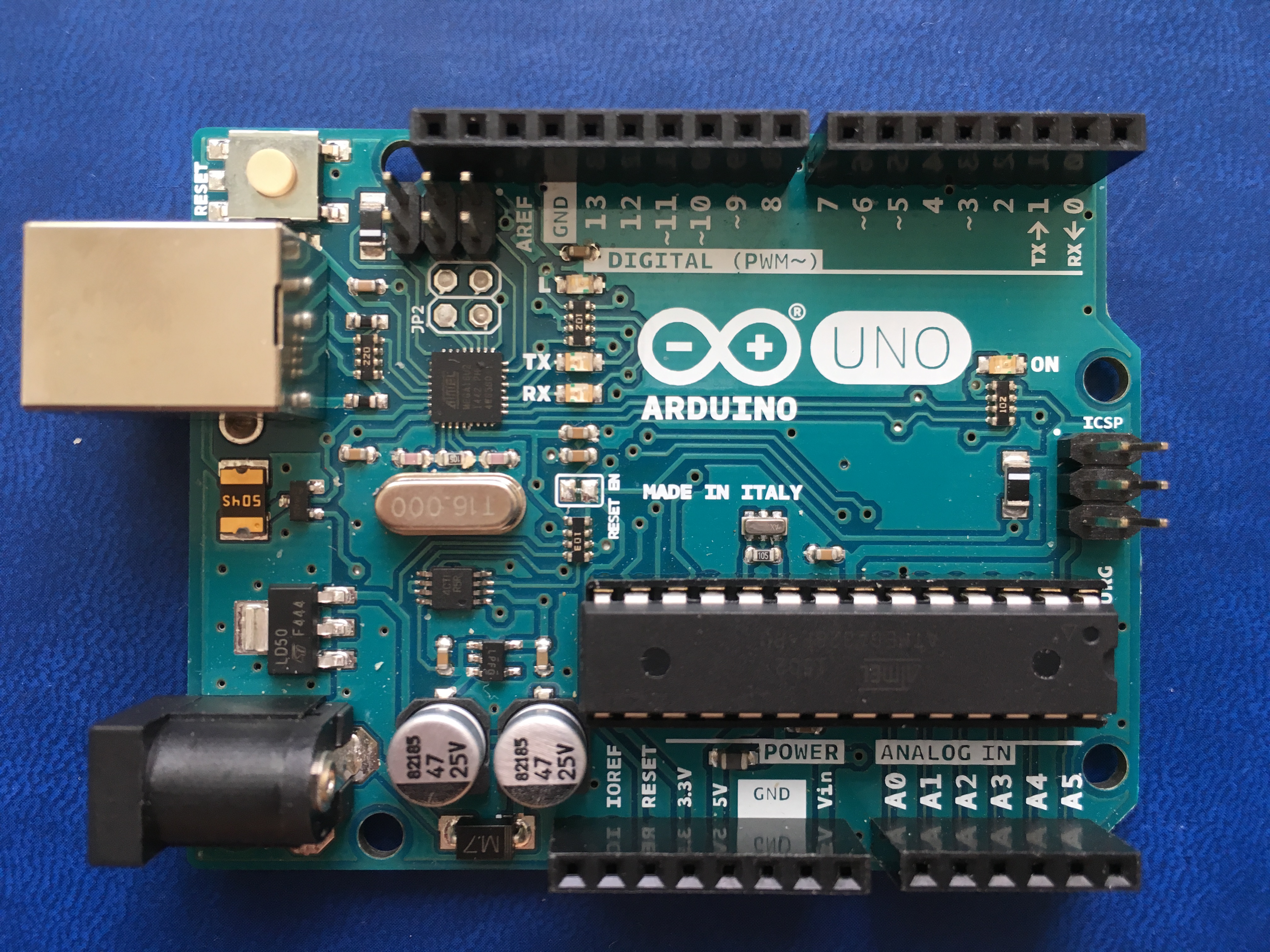
- 1 x Arduino UNO
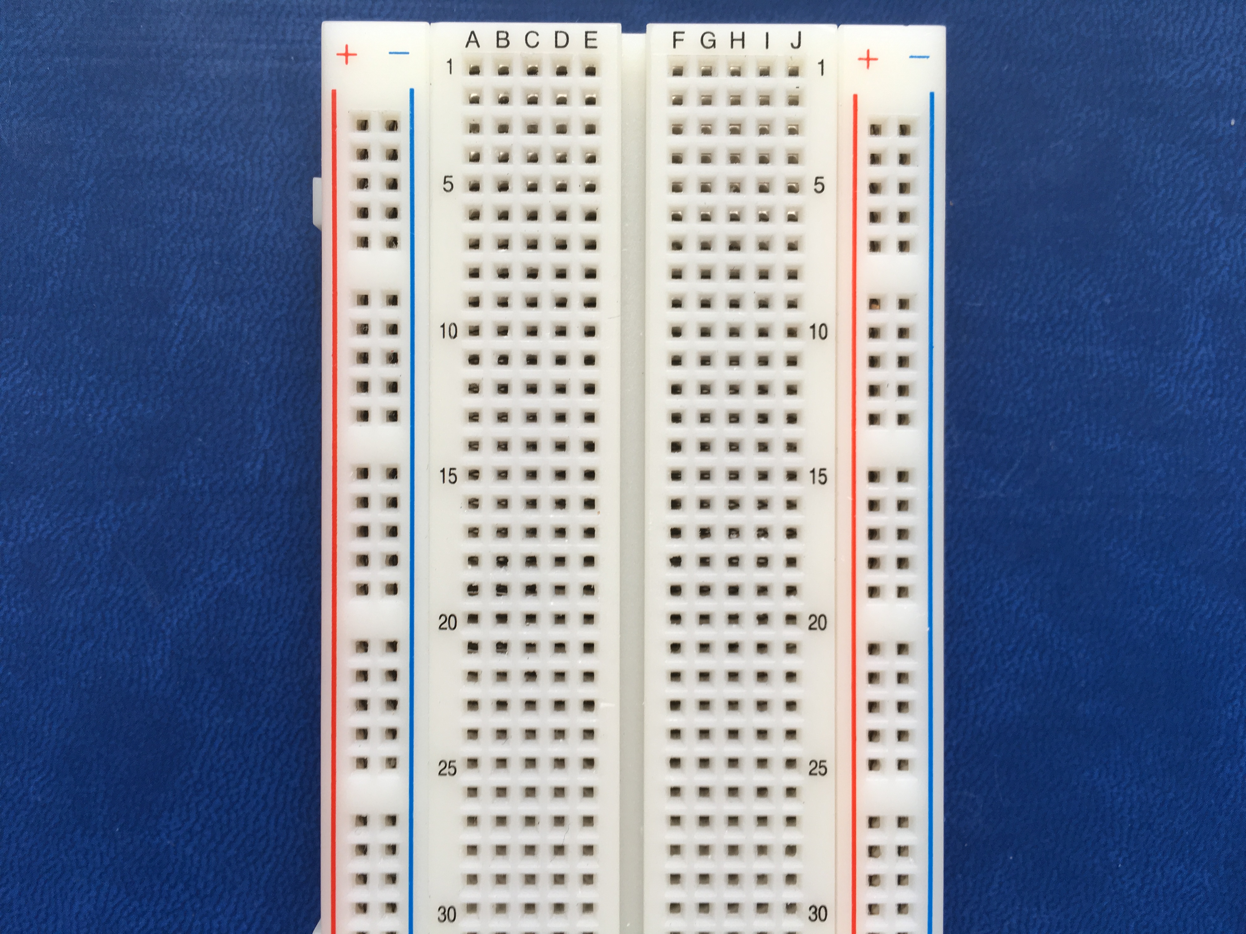
- 1 x Breadboard
- 1 x DC motor
- 1 x 9-volt battery
- 1 x H-bridged IC
- 2 x Switches
- 2 x 10-kilohm resistors
- 1 x Rotary potentiometer
- 1 x Battery snap
- 17 x Jumper wires
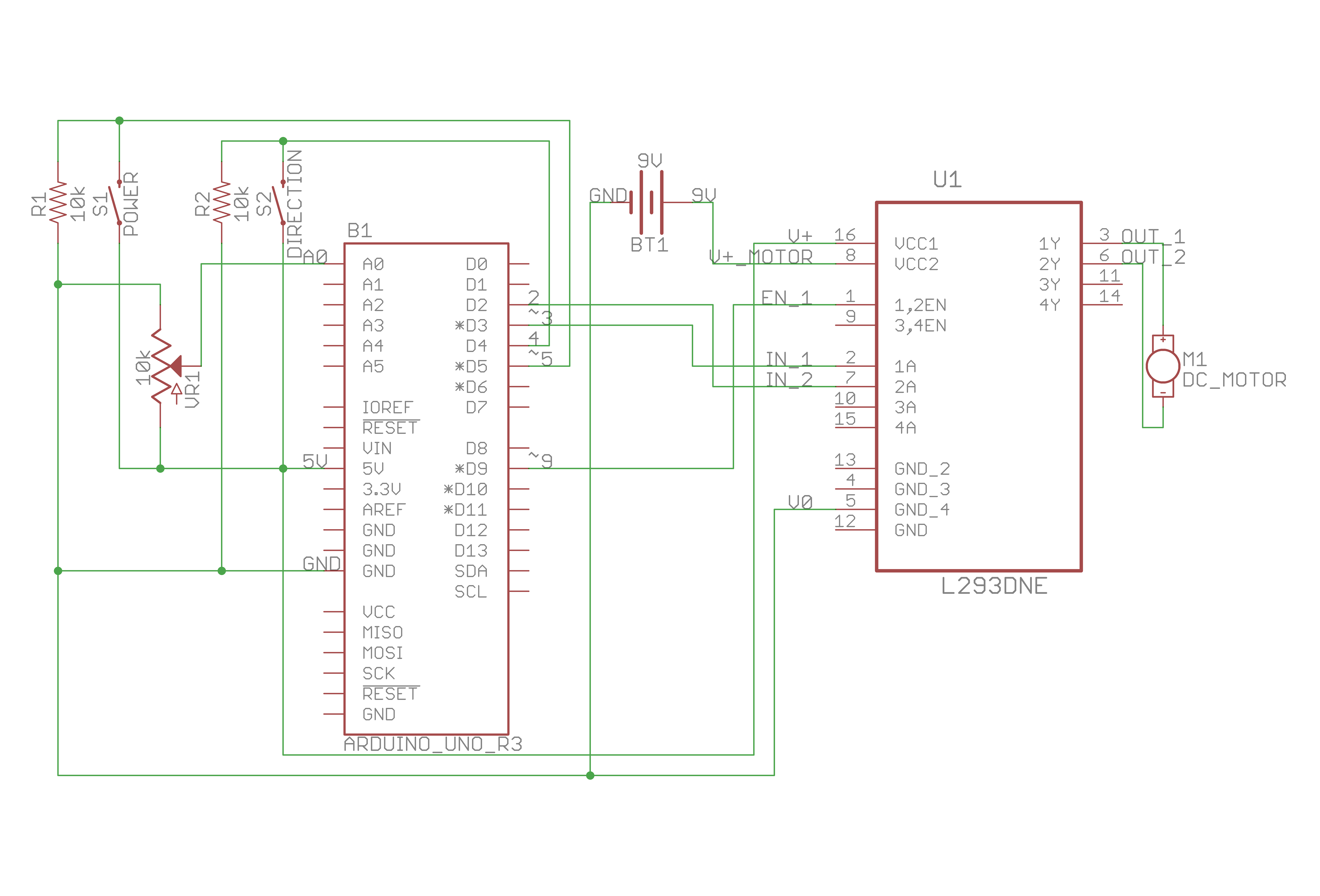
CIRCUIT:
As usual, here is the schematic:
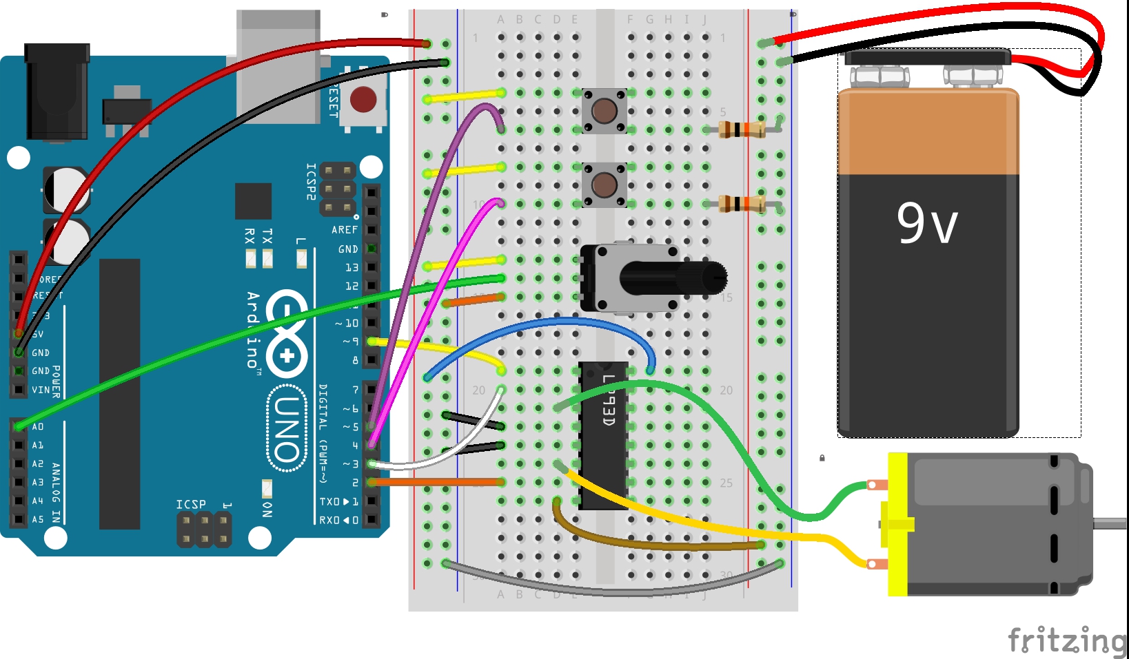
And this is the virtual layout of my breadboard:
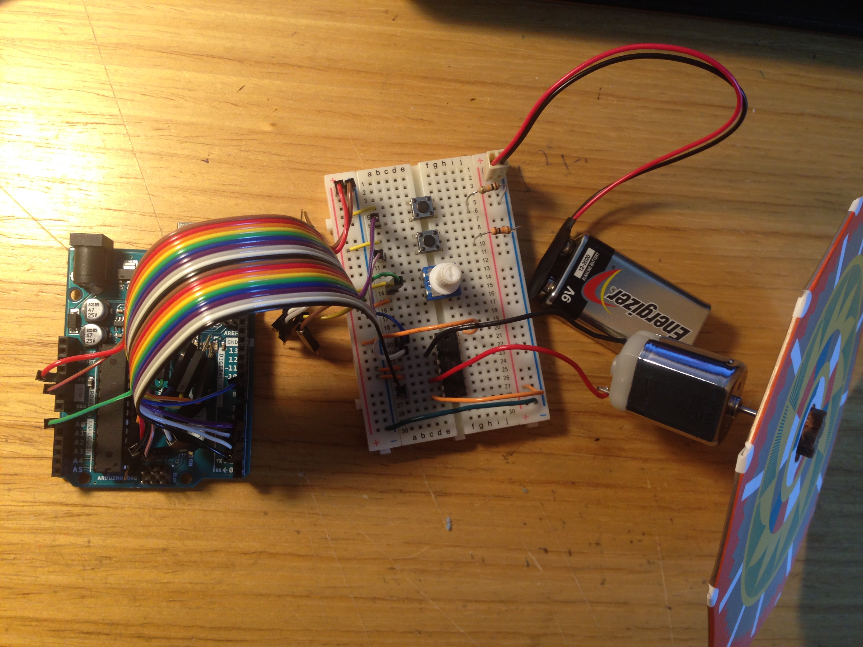
Finally, this is how I wired my circuit:
CODE:
Here is the code:
1
2
3
4
5
6
7
8
9
10
11
12
13
14
15
16
17
18
19
20
21
22
23
24
25
26
27
28
29
30
31
32
33
34
35
36
37
38
39
40
41
42
43
44
45
46
47
48
49
50
51
52
53
54
55
56
57
58
59
60
61
62
63
64
65
66
67
68
69
70
71
72
73
74
75
76
77
78
79
/**
 * Project Name: Arduino Projects Book - Project 10: Zoetrope
 *
 * File Name: zoetrope.ino
 *
 * Description: Controls the speed and the direction of the DC motor using
 * two switches and a potentiometer.
 *
 * Author: Zhengqi Dong
 * Location:
 * Created: August 21, 2016
 * Updated: June 22, 2017
 */

// Required hardware I/O connections
const byte POT_PIN              = A0; // connect potentiometer to A0
const byte IC_INPUT_1           = 3;  // connect IC Input1 to ~3
const byte IC_INPUT_2           = 2;  // connect IC Input2 to 2
const byte IC_ENABLE_1          = 9;  // connect IC Enable1 t ~9
const byte DIRECTION_SWITCH_PIN = 4;  // connect direction switch to 4
const byte STATE_SWITCH_PIN     = 5;  // connect state switch to ~5

// Global variables
byte state_switch_val          = 0;   // state switch
byte direction_switch_val      = 0;   // direction switch
byte prev_state_switch_val     = 0;   // previous state switch
byte prev_direction_switch_val = 0;   // previous direction switch
byte motor_is_enabled          = 0;   // whether the motor is on/off
byte motor_direction           = 0;   // motor direction
unsigned short motor_speed     = 0;

void setup() {
    pinMode(DIRECTION_SWITCH_PIN, INPUT);
    pinMode(STATE_SWITCH_PIN,     INPUT);
    pinMode(IC_INPUT_1,           OUTPUT);
    pinMode(IC_INPUT_2,           OUTPUT);
    pinMode(IC_ENABLE_1,          OUTPUT);
}

void loop() {
    state_switch_val = digitalRead(STATE_SWITCH_PIN);
    delay(1);
    direction_switch_val = digitalRead(DIRECTION_SWITCH_PIN);
    motor_speed          = analogRead(POT_PIN) / 4;

    // process the on/off state of the motor from the state switch
    if (state_switch_val != prev_state_switch_val) {
        if (state_switch_val) {
            motor_is_enabled = !motor_is_enabled;
        }
    }

    // process the direction of the motor from the direction switch
    if (direction_switch_val != prev_direction_switch_val) {
        if (direction_switch_val) {
            motor_direction = !motor_direction;
        }
    }

    // control the direction of the motor using the IC
    if (motor_direction) {
        digitalWrite(IC_INPUT_1, LOW);
        digitalWrite(IC_INPUT_2, HIGH);
    } else {
        digitalWrite(IC_INPUT_1, HIGH);
        digitalWrite(IC_INPUT_2, LOW);
    }

    // control the on/off state of the motor using PWM
    if (motor_is_enabled) {
        analogWrite(IC_ENABLE_1, motor_speed);
    } else {
        analogWrite(IC_ENABLE_1, 0);
    }

    // prep for next inputs
    prev_state_switch_val     = state_switch_val;
    prev_direction_switch_val = direction_switch_val;
}
