OVERVIEW:
Welcome back! Today I’ll get the Arduino to spin a colorful pinwheel using a DC motor. In this project, we will use the DC motor for the first time with the Arduino. Working with a DC motor is fun because I can make things move using electronics. However, there are some important details that I think I should take a careful note. Let’s begin with a new component–the transistor.
TRANSISTORS:
Transistors are components that allow us to control high current and high voltage from the low current output of microcontrollers, especially Arduino. There are many different kinds of a transistor, but they usually fall into two categories: NPN and PNP transistors.
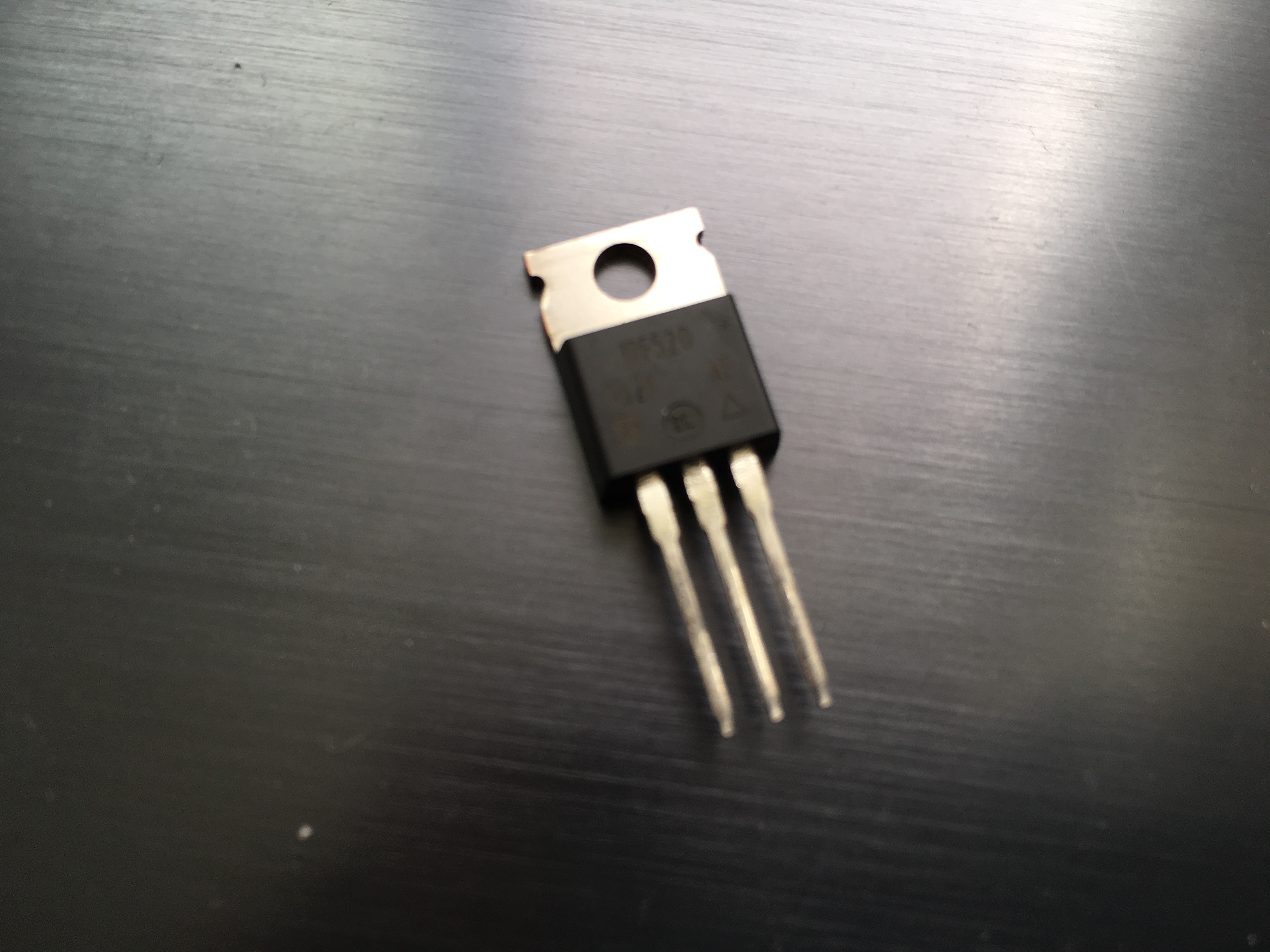
When we provide voltage to one of the transistor’s pins, called the gate, it closes the circuit between the other two pins, which are the source and the drain. I would say the physical switch and this transistor have a correlation. In other words, transistors are digital switches or “a smarter switch”. Next, let’s take a look at the DC motor.
DC MOTORS:
Motors are the type of inductive device. But, what exactly is induction? Induction is a process by which a changing electrical current in a wire can create a magnetic field around the wire. When we supply voltage to the DC motor, its coil generates a magnetic field. This field causes the shaft to spin around.
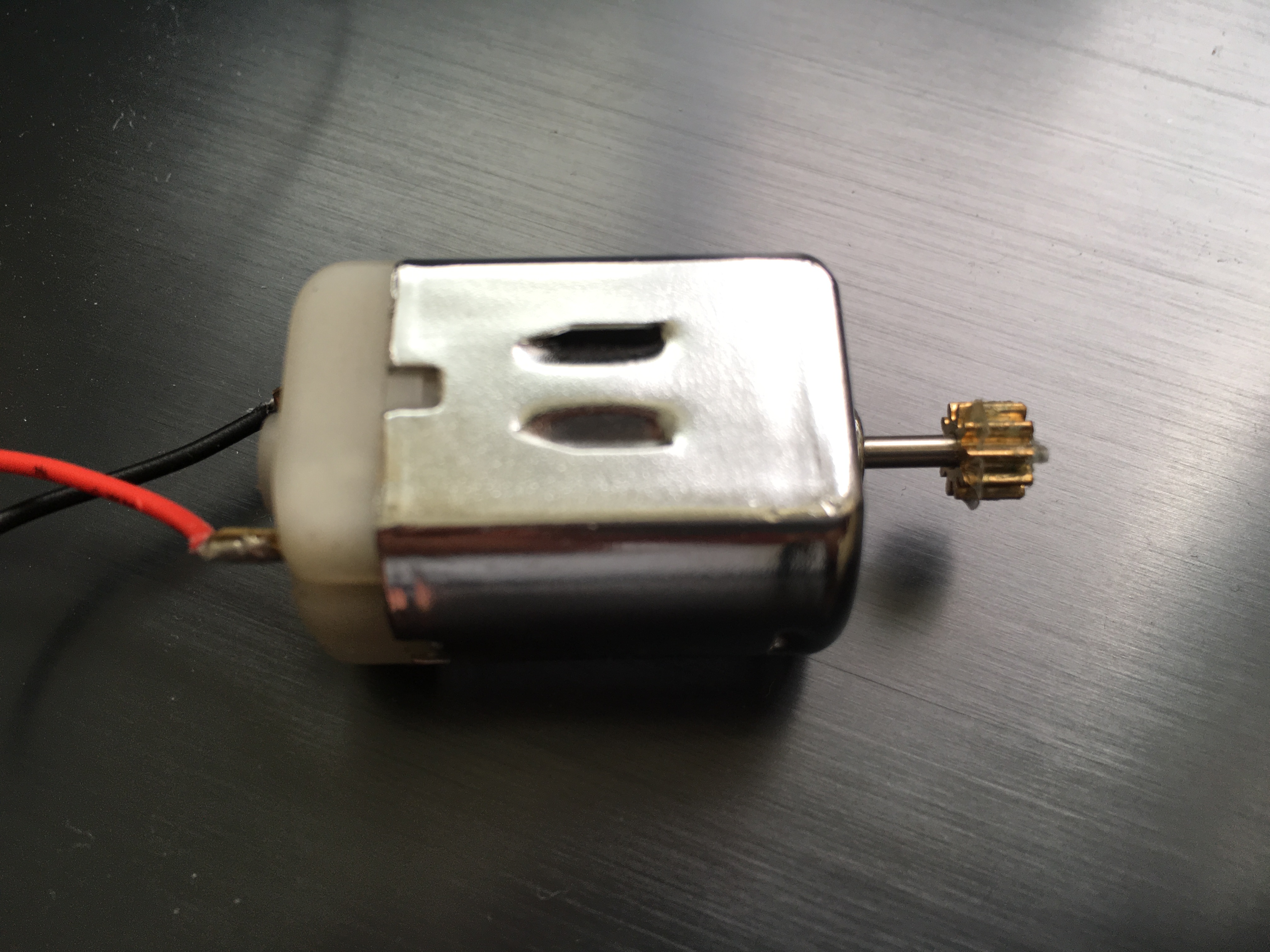
Nevertheless, when we turn off the motor, it doesn’t stop immediately due to inertia. A motor can create electricity when it’s spinning, and the current generated will be in the opposite direction of the original current–which could lead to damaging the components.
To solve this problem, we must connect a diode parallel to the DC motor such that the anode (+) points to the original current and the cathode (-), which has a band on it, points to the motor. The diode only allows the current to flow in one direction (from the anode to the cathode but not the other way around), and so we can apply this attribute to prevent the inductive current from damaging the transistor (or more badly, the Arduino).
The concepts in this project are a bit complicated, but the program and the usage are fairly easy.
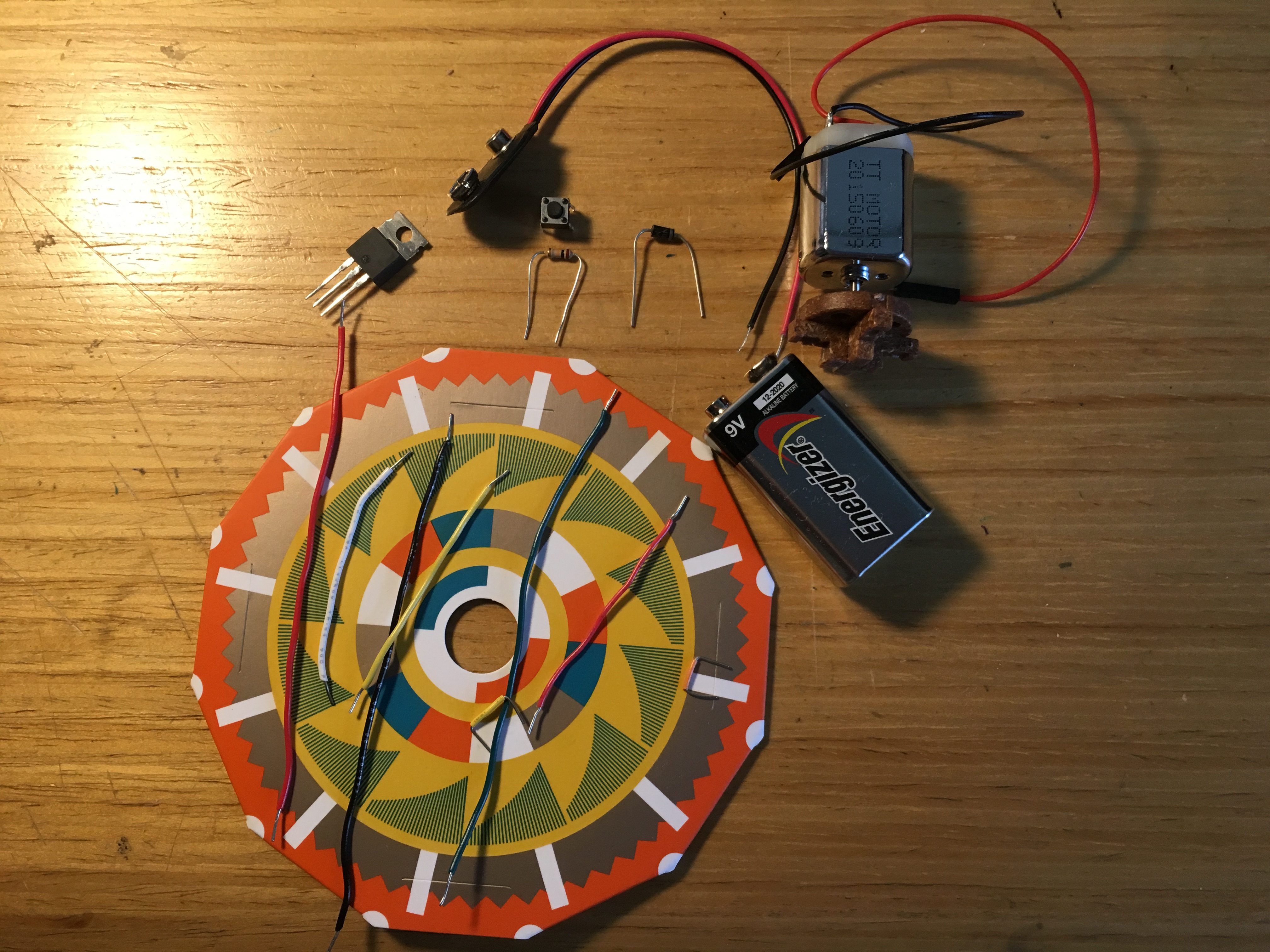
PARTS:
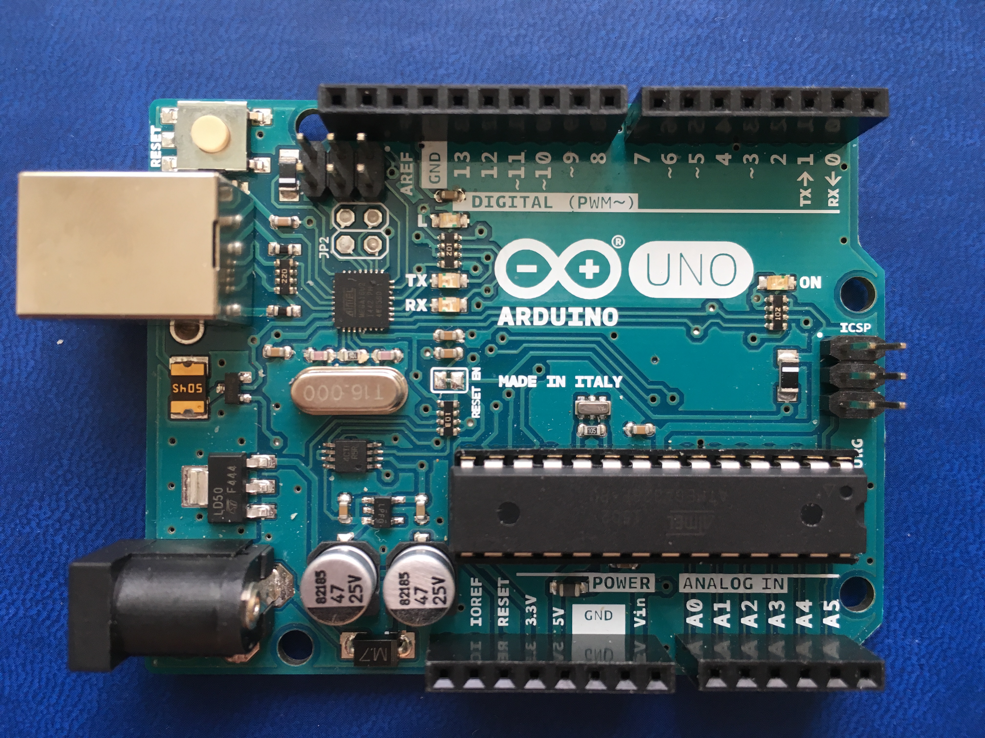
- 1 x Arduino UNO
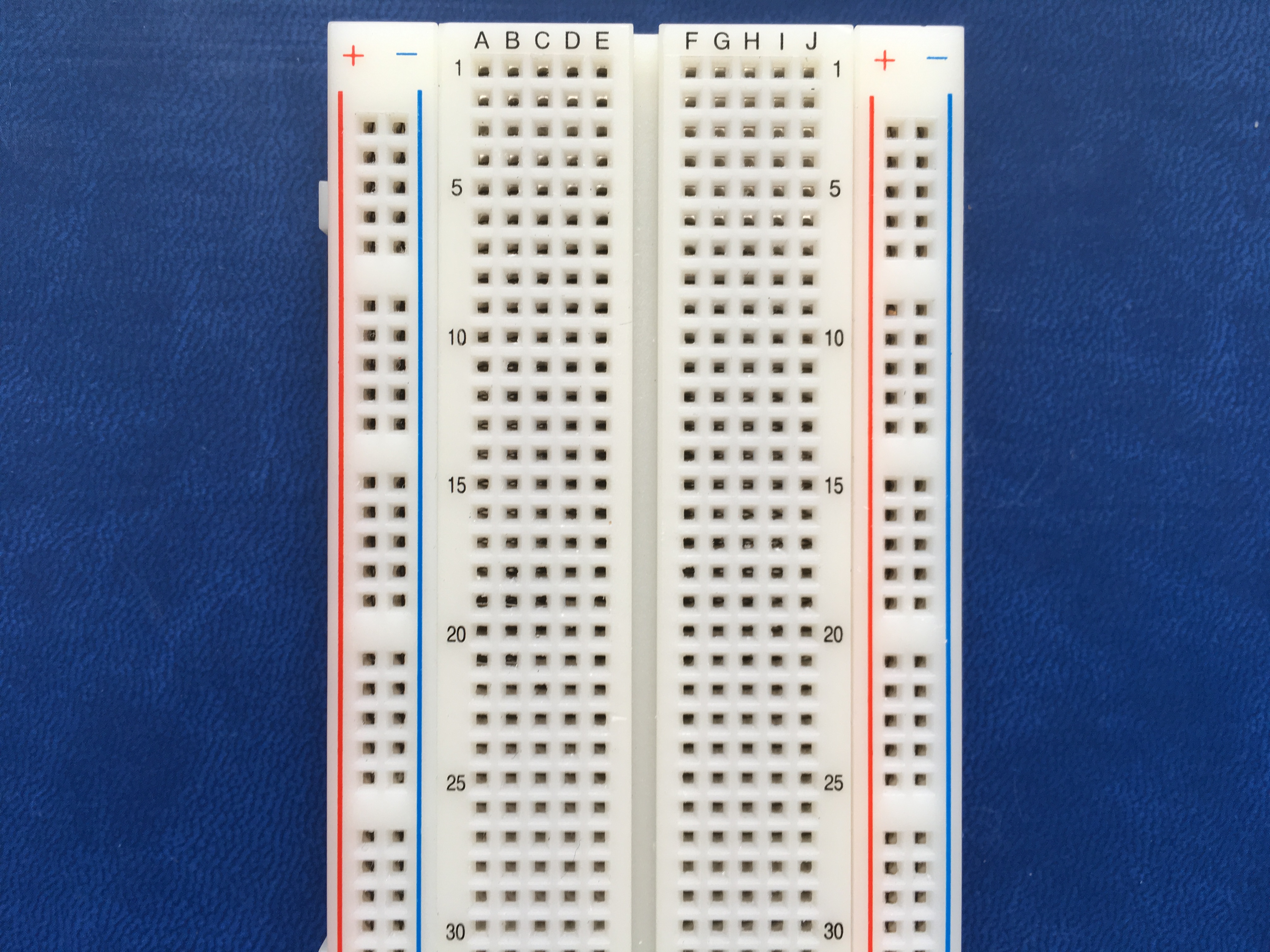
- 1 x Breadboard
- 1 x MOSFET transistor
- 1 x Switch
- 1 x 10-kilohm resistor
- 1 x Diode (1N4007)
- 1 x DC Motor
- 1 x 9-volt battery
- 1 x Battery snap
- 1 x Motor wheel & 1 x Colorful wheel (Optional)
- 8 x Jumper wires
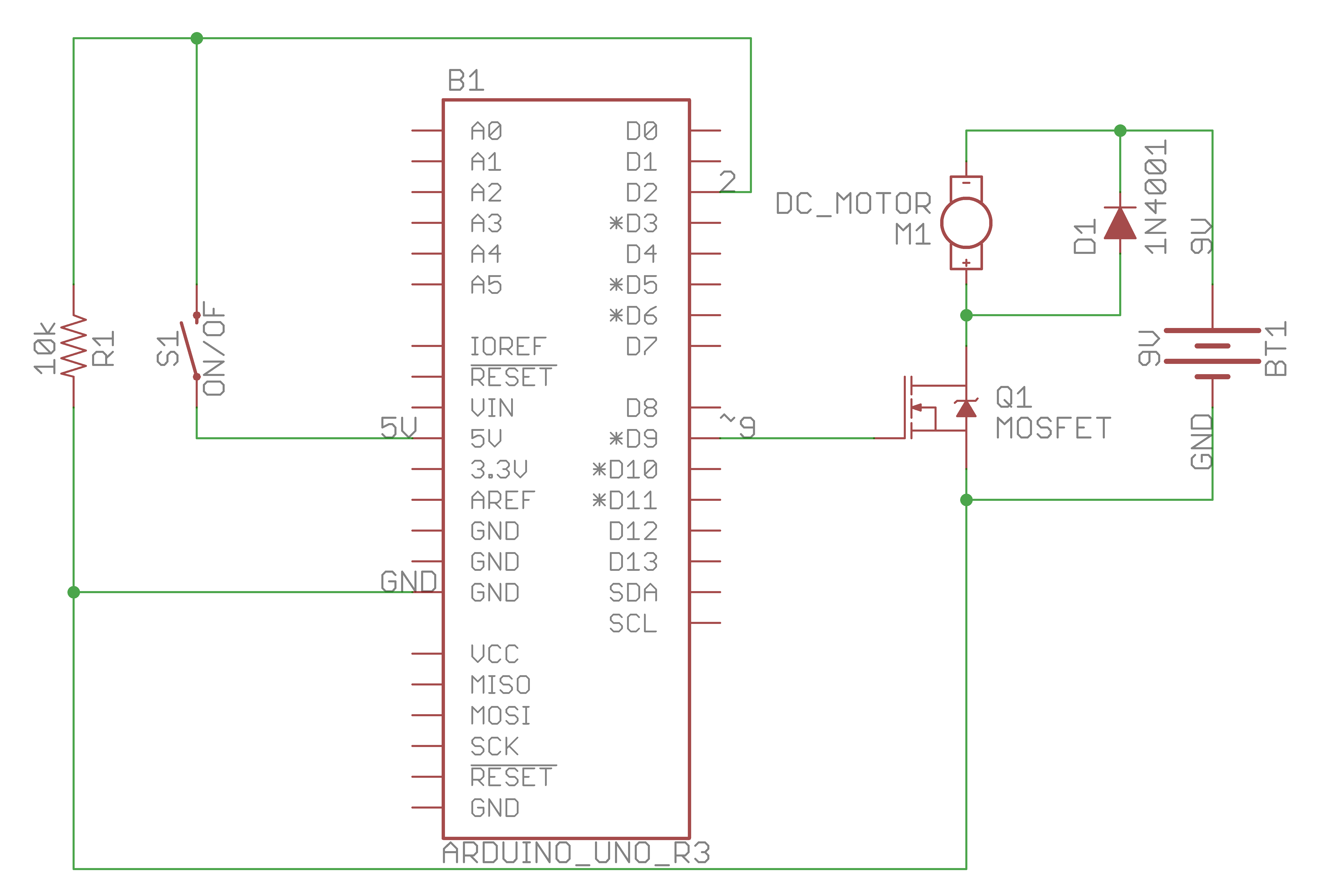
CIRCUIT:
Schematic:
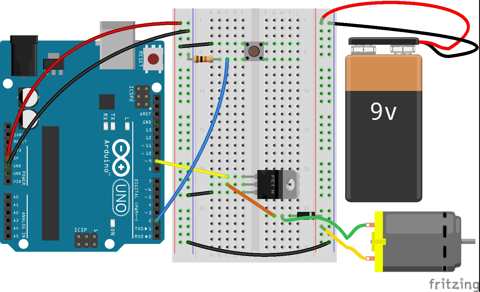
Virtual breadboard layout by Fritzing:
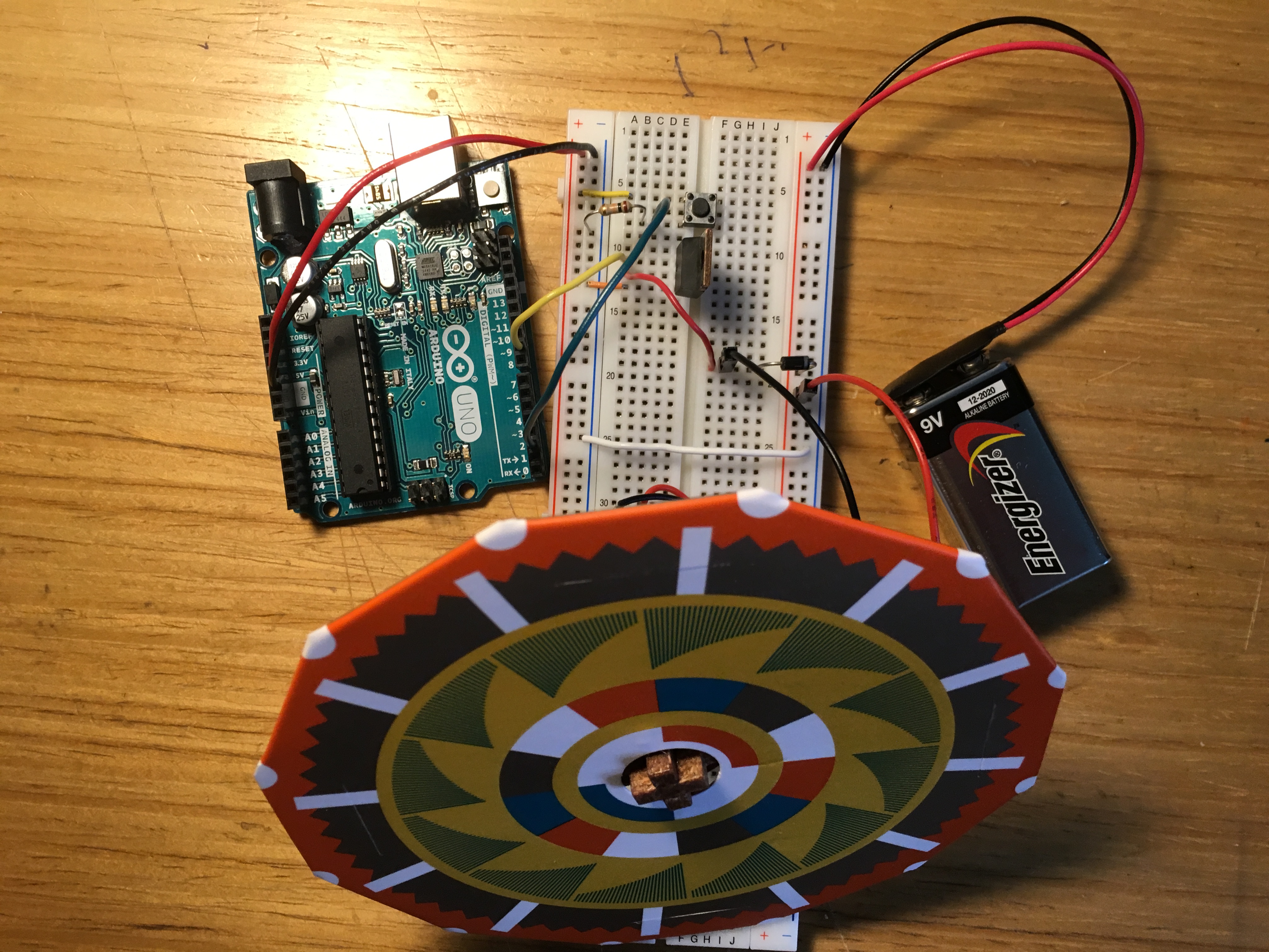
Here is my circuit layout:
CODE:
Here is the code:
1
2
3
4
5
6
7
8
9
10
11
12
13
14
15
16
17
18
19
20
21
22
23
24
25
26
27
28
29
30
31
32
/**
 * Project Name: Arduino Projects Book - Project 09: Motorized Pinwheel
 *
 * File Name: motorized_pinwheel.ino
 *
 * Description: Gets the Arduino to spin a colorful pinwheel using a motor.
 *
 * Author: Zhengqi Dong
 * Location:
 * Created: August 13, 2016
 * Updated: June 22, 2017
 */

// Required hardware I/O connections
const byte SWITCH_PIN = 2; // connect switch to 2
const byte MOTOR_PIN  = 9; // connect dc motor to ~9

void setup() {
    pinMode(SWITCH_PIN, INPUT);
    pinMode(MOTOR_PIN,  OUTPUT);
}

void loop() {
    byte switch_state = digitalRead(SWITCH_PIN);

    // toggle the switch to toggle the motor
    if (switch_state) {
        digitalWrite(MOTOR_PIN, HIGH);
    } else {
        digitalWrite(MOTOR_PIN, LOW);
    }
}
