OVERVIEW:
Today, I become a musician! I’ll use light to control the piezo buzzer. It’s going to be a fun project since the piezo produces some funny sound. The instrument which I’m building is called a theremin. It’s time for the sixth project of the Arduino Projects Book - Light Theremin.
PARTS:
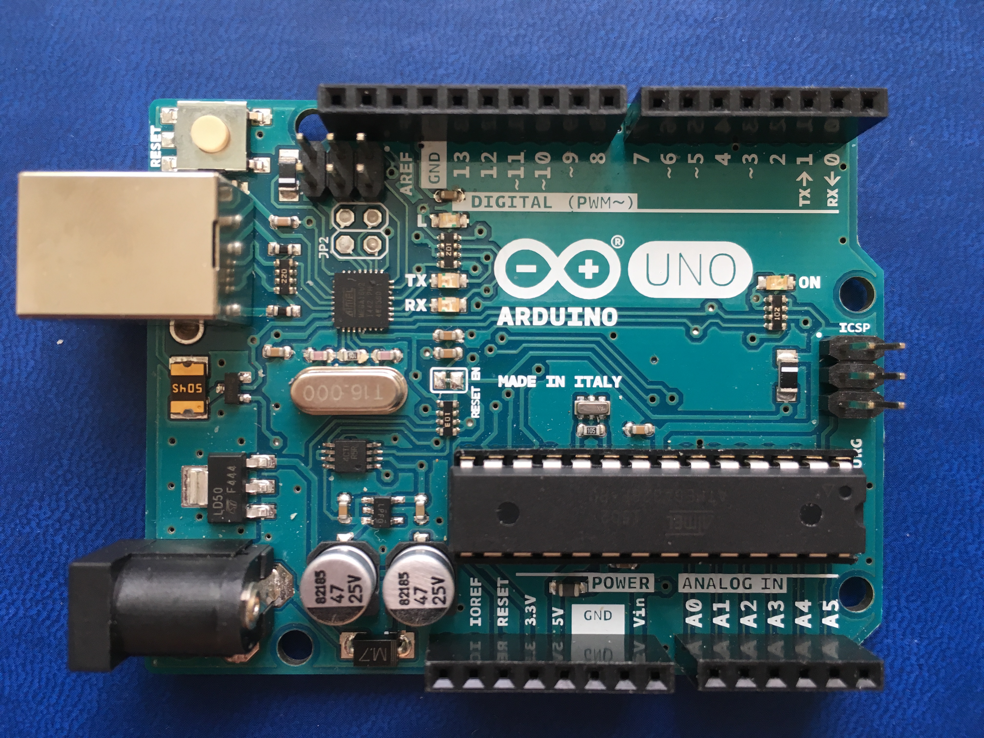
- 1 x Arduino UNO
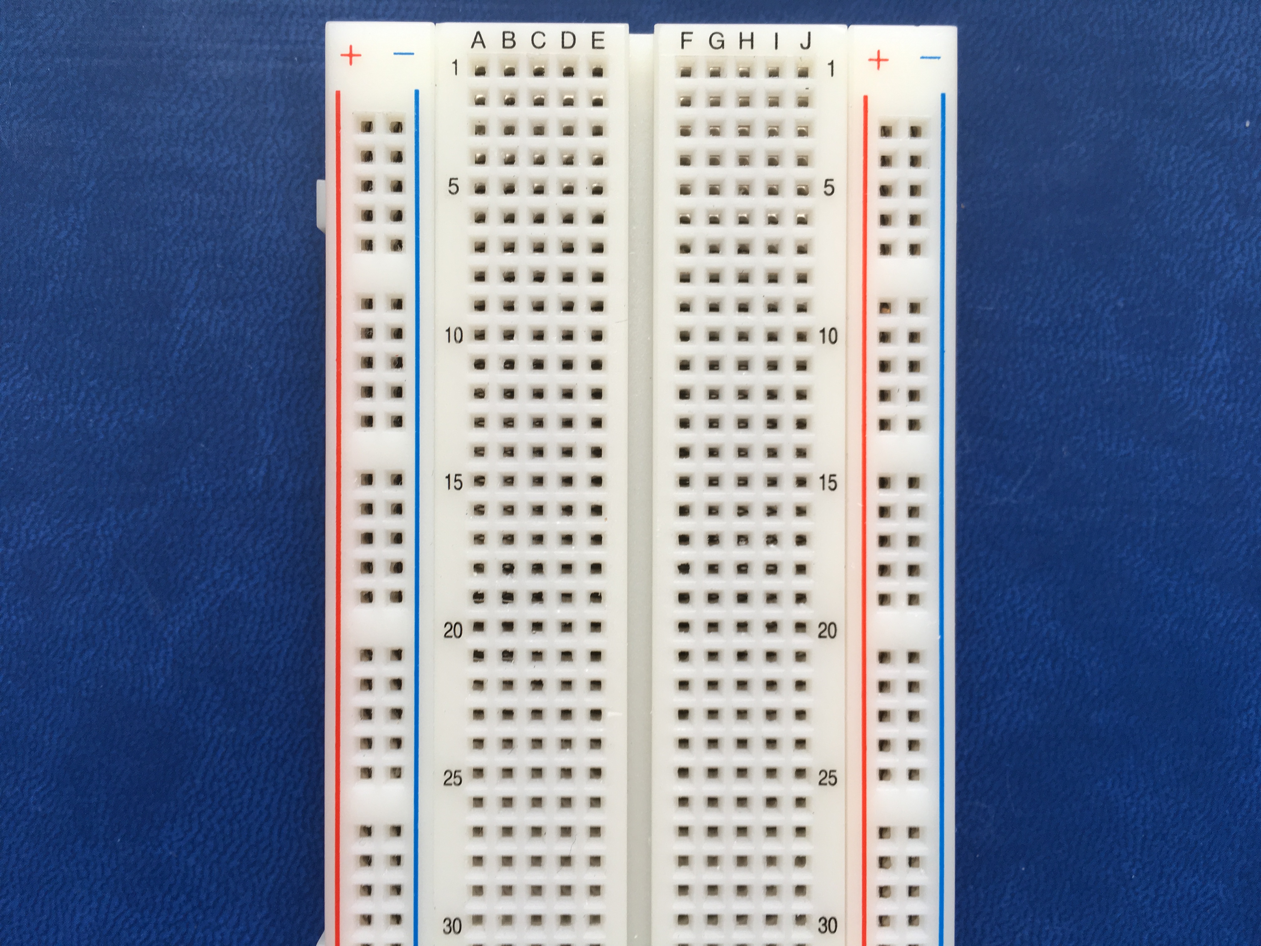
- 1 x Breadboard
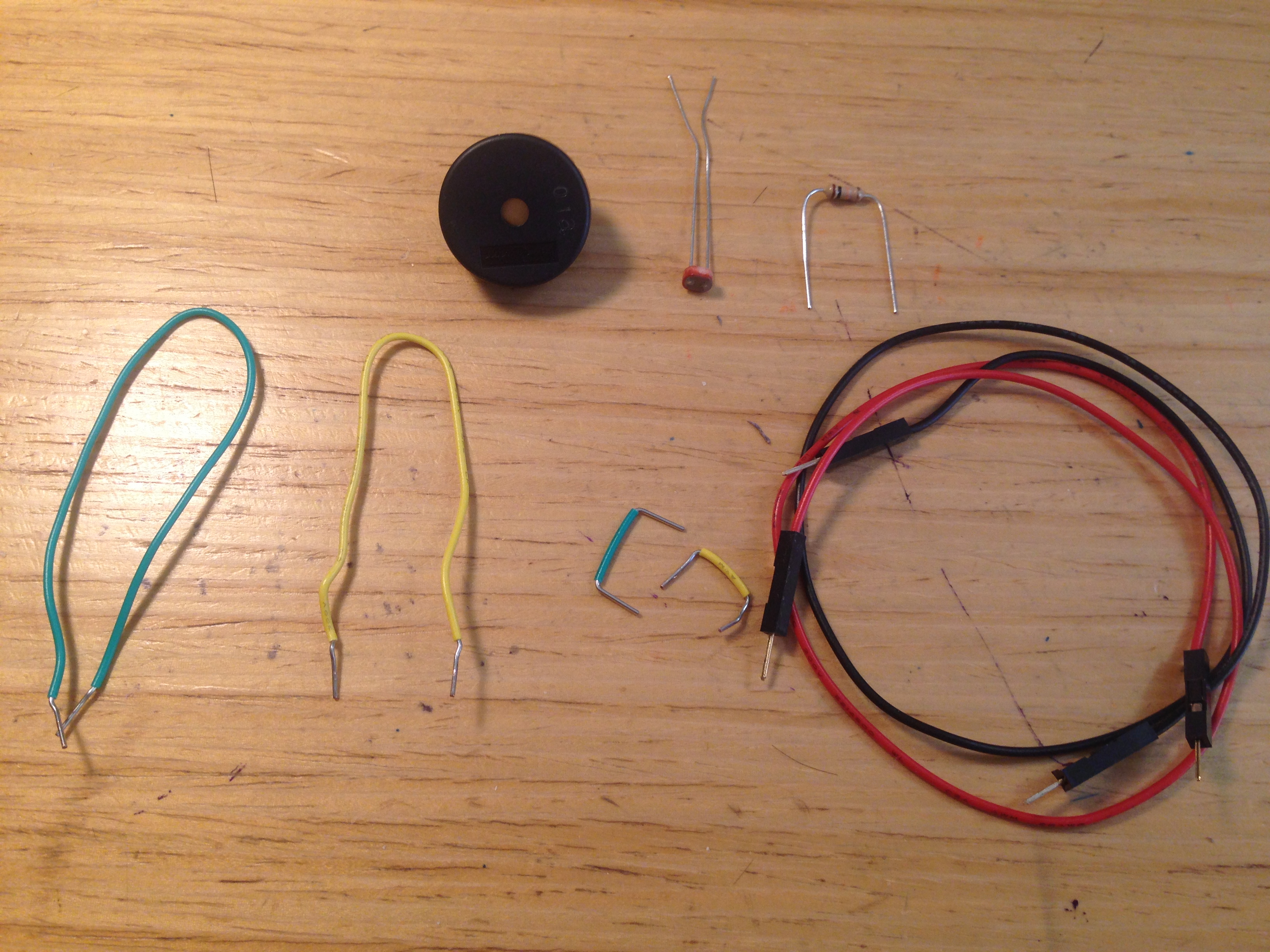
- 1 x Piezo buzzer
- 1 x Photocell
- 1 x Red LED (Optional)
- 1 x 220-ohm resistor (Optional)
- 1 x 10-kilohm resistor
- 7 x Jumper wires
BREADBOARD LAYOUT:
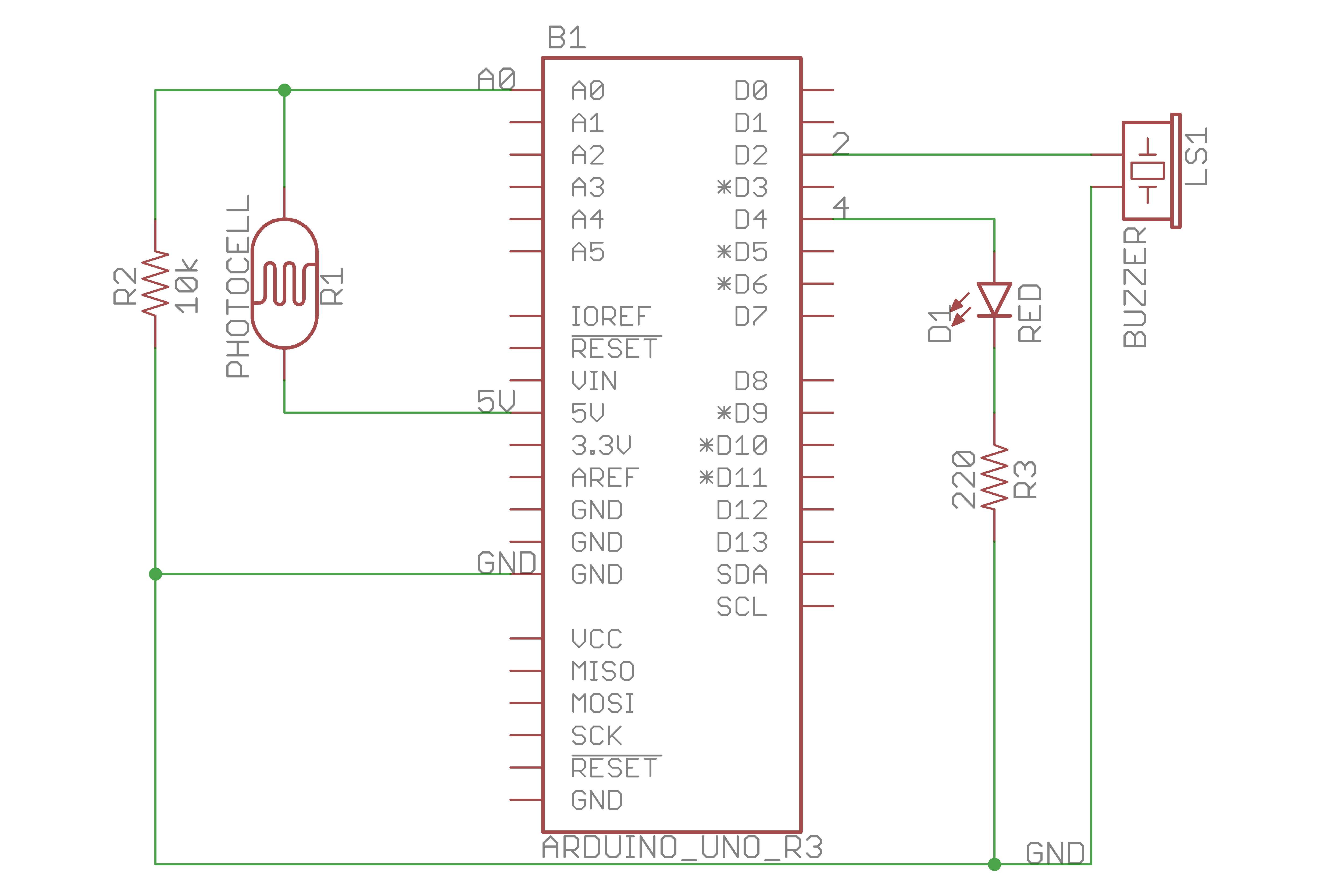
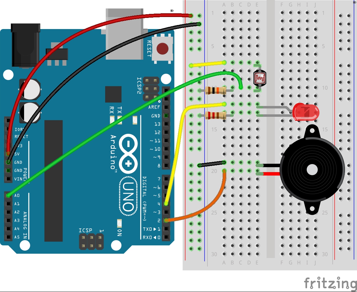
It’s quite easy to build the circuit. As usual, the photocell always goes with a 10-kilohm resistor, and the LED always goes with a 220-ohm resistor. We don’t need any resistor for the Piezo, though.
Below are my schematic and virtual breadboard layout.
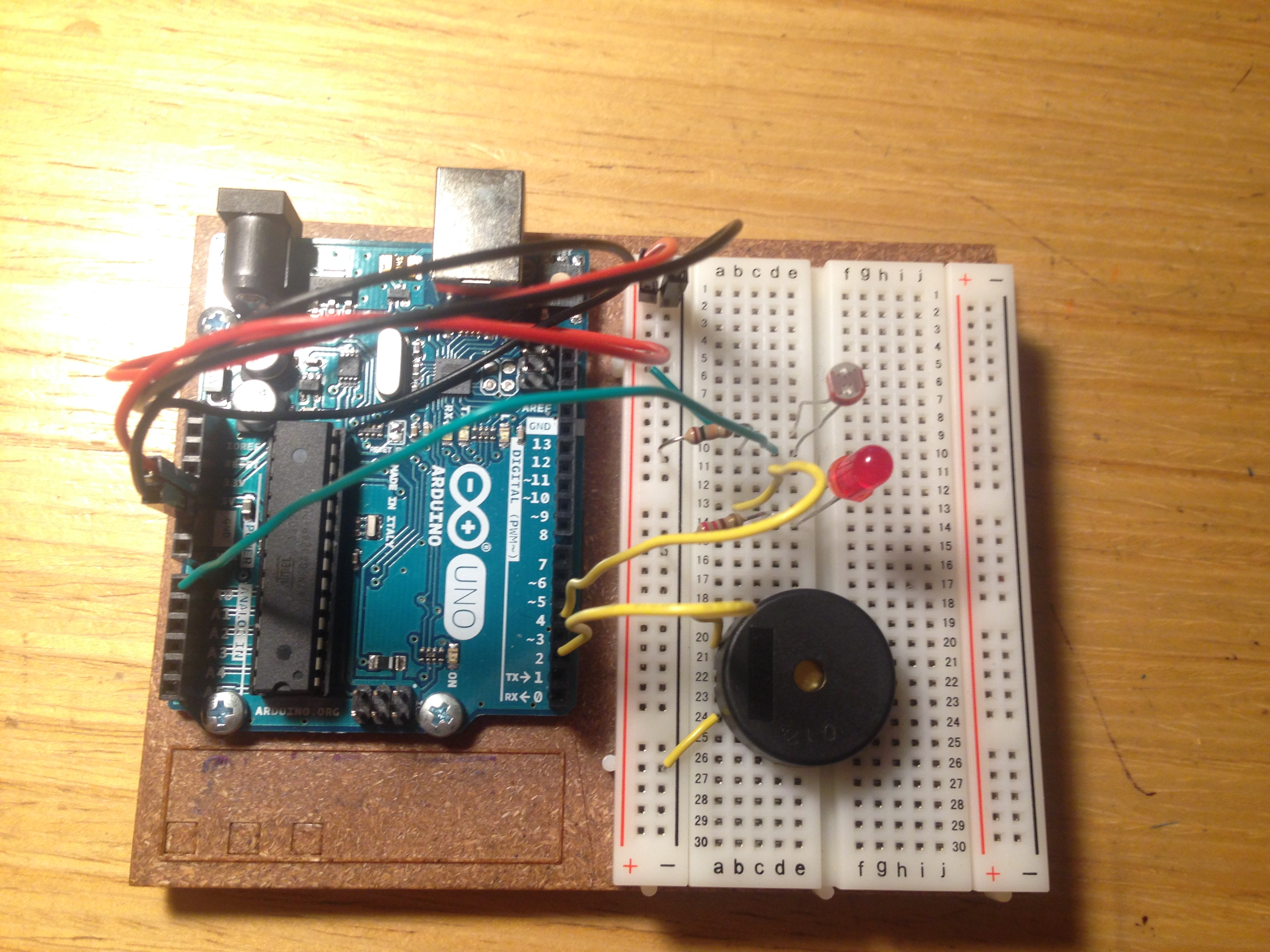
Here is my real-board layout:
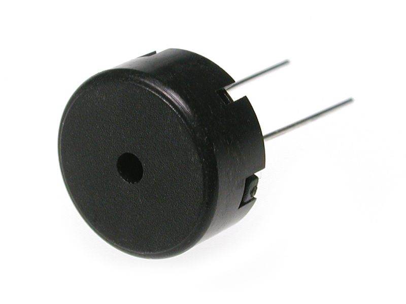
PIEZO BUZZER:
A piezo buzzer is a small element that vibrates when it receives electricity. When it moves, it displaces air around it, creating sound waves.
Piezo only has 2 leads. One lead connects to a digital pin, and the other connects to ground.
ARDUINO CODE:
There are new functions that will be used in this project, millis() and tone().
unsigned long time = millis();
millis() is a time built-in function that reports how long the Arduino has been running since it was last powered on or reset, in milliseconds. In order to apply millis() into this project, I use a while() loop with a condition millis() <= 5000, which means 5 seconds since the Arduino has been running. Five seconds should be enough for calibrating the photocell.
tone(BUZZER_PIN, frequency, duration);
tone() helps us make sound with the piezo buzzer. It takes three arguments: what pin to play the sound on (in this case pin 2), what frequency to play (determined by the pitch variable), and how long to play the note (let’s try 20 milliseconds).
Here is the code:
1
2
3
4
5
6
7
8
9
10
11
12
13
14
15
16
17
18
19
20
21
22
23
24
25
26
27
28
29
30
31
32
33
34
35
36
37
38
39
40
41
42
43
44
45
46
47
48
49
50
51
52
53
/**
 * Project Name: Arduino Projects Book - Project 06: Light Theremin
 *
 * File Name: light_theremin.ino
 *
 * Description: Makes a light-based theremin using photocells and a buzzer.
 *
 * Author: Zhengqi Dong
 * Location:
 * Created: January 10, 2016
 * Updated: June 22, 2017
 */

// Required hardware I/O connections
const byte SENSOR_PIN = A0; // connect photocell to A0
const byte PIEZO_PIN  = 2;  // connect buzzer to 2
const byte LED_PIN    = 4;  // connect LED to 4

// Global variables
unsigned int sensor_val;
unsigned int sensor_high = 0;    // initial min of the photocell
unsigned int sensor_low  = 1023; // initial max of the photocell

void setup() {
    pinMode(PIEZO_PIN, OUTPUT);
    pinMode(LED_PIN,   OUTPUT);
    // calibrate the photocell for 5 seconds - red light turned on
    digitalWrite(LED_PIN, HIGH);

    while (millis() < 5000) {
        sensor_val = analogRead(SENSOR_PIN);

        if (sensor_val > sensor_high) {
            sensor_high = sensor_val; // set new max value
        }

        if (sensor_val < sensor_low) {
            sensor_low = sensor_val; // set new min value
        }
    }
    // calibration completed - red light turned off
    digitalWrite(LED_PIN, LOW);
}

void loop() {
    sensor_val = analogRead(SENSOR_PIN);
    // determine the pitch of the piezo
    unsigned int pitch = map(sensor_val, sensor_low, sensor_high, 50, 4000);
    // play the piezo with the pitch for 20 milliseconds
    tone(PIEZO_PIN, pitch, 20);
    // wait 10ms for the sensor to stabilize
    delay(10);
}
